Blog

What Are the Top Types of CNC Turning?

CNC turning is not a single operation with one setup and one predictable result. It is a family of machining methods that shape rotating workpieces, from simple shafts to parts with angled faces, grooves, and precise threads. The right method depends on the part’s geometry, material, tolerance, batch size, and finishing needs. A small choice can matter: a live tool may mill a flat feature without moving the part to another machine, while a Swiss-type lathe supports slender components close to the cutting zone.

Manufacturing researcher Dr. David A. Dornfeld has emphasized looking beyond an individual tool to the machining process as a whole. A concise paraphrase of that perspective is: “Reliable machining depends on the complete process, not one cutting tool.” That distinction helps explain why CNC turning types are best compared by their capabilities and constraints, not by machine labels alone. Even a capable machine can produce chatter, burrs, or inconsistent dimensions when the setup is poorly matched to the workpiece.

This guide explores conventional CNC turning, Swiss-type turning, multi-axis turning, and related methods. It also considers where each approach fits, what features it can produce, and which trade-offs deserve attention. Some applications overlap. That is normal. The best choice is not always the most advanced machine; it is the one that meets the part’s requirements consistently, with a process the shop can verify and repeat.
What Are the Top Types of CNC Turning?

How CNC Turning Operations Are Classified

What Are the Top Types of CNC Turning?

How CNC Turning Operations Are Classified

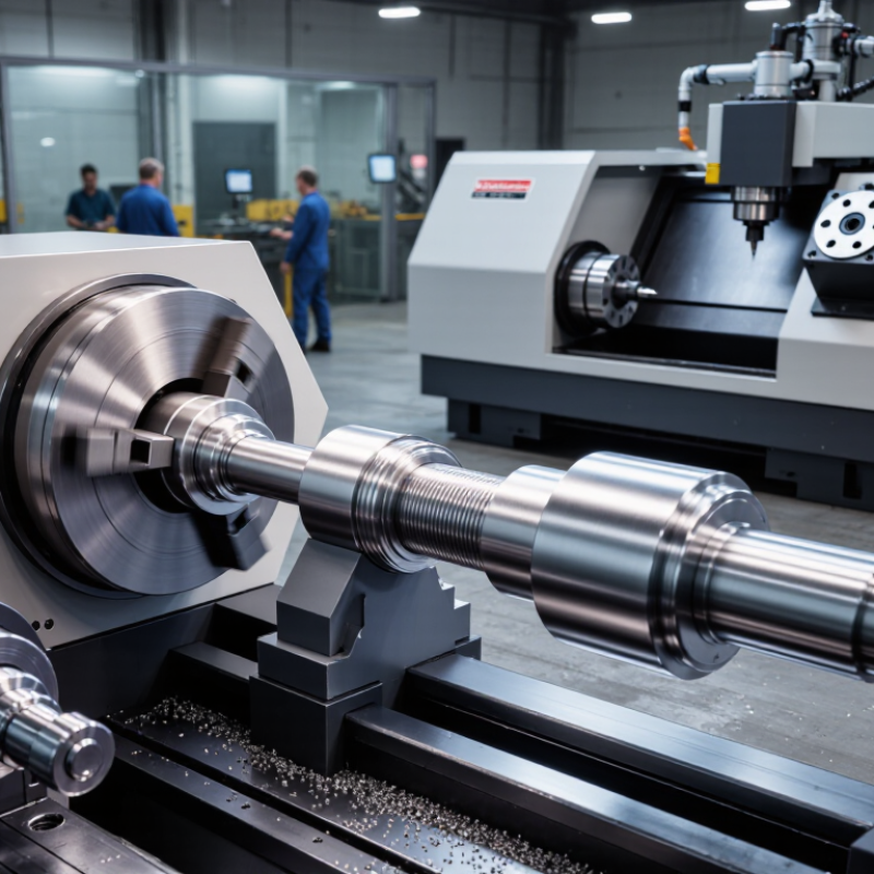
CNC turning is best classified by what the cutting tool does to rotating stock. External turning reduces a part’s diameter; facing squares its end; grooving cuts a narrow channel; and parting separates the finished piece. Threading forms a helix, while boring enlarges an existing hole.

Short cuts, distinct results.

A second classification looks at machine setup and tool movement. Basic two-axis lathes move tools along the X and Z directions. Multi-axis machines may add live tooling or a sub-spindle, allowing features such as cross-holes or flats with fewer setups.

Grand View Research estimated the global CNC machine market at $83.99 billion in 2023 and forecast 9.5% annual growth from 2024 to 2030 in its CNC Machine Market report. This covers CNC machines broadly, not turning alone. It signals wider investment, not a turning-specific market share.

Tips: Mark each drawing feature as external, internal, face, groove, or thread. Then check tool access and clearance. Categories can overlap, so review the actual toolpath.

Straight Turning and Contour Turning

Straight turning reduces a rotating workpiece to a consistent diameter, with the cutting tool moving parallel to its axis. It suits shafts, sleeves, and stepped parts with long cylindrical sections. A machinist sets the depth of cut, feed rate, and spindle speed to balance material removal and surface finish. Small details matter. A tool that is slightly worn can leave visible lines or push a thin part out of shape. Support the workpiece carefully, especially when it extends far beyond the chuck.

Contour turning follows a programmed path to create tapers, radii, grooves, and other changing profiles. The tool moves across and along the part, so the setup must account for tool-nose radius, clearance, and chip removal. One pass helps, but it is not always the best choice. Roughing and finishing passes can improve control on complex forms. Grand View Research’s 2024 CNC machine market report valued the global market at USD 101.22 billion in 2023 and forecast 9.5% annual growth through 2030. This broad market figure signals expanding CNC use, not turning-specific demand. For either method, check the finished part against the drawing; a smooth surface alone does not confirm dimensional accuracy.

Facing, Grooving, and Parting Operations

Facing, grooving, and parting each remove material differently, so tool approach and chip control matter. Facing cuts across the end of a rotating workpiece, creating a flat reference surface. Keep the tool path controlled toward the center; cutting speed changes as the tool moves inward. A steady setup helps limit chatter and uneven finish.

Grooving forms a narrow channel, often for a retaining ring or seal. Match the insert width to the drawing, and clear chips before they pack into the groove. Parting separates the finished component from the bar. It is less forgiving: a long tool overhang or off-center tip can cause vibration, burrs, or a broken insert. Short overhang matters. For finish planning, Machinery’s Handbook, 31st edition, gives the ideal turning estimate Ra ≈ f²/(32r), where f is feed per revolution and r is tool-nose radius. It is a useful starting point, not a promise; material, insert geometry, and machine rigidity change actual results. ISO 21920-2:2021 defines profile surface-texture parameters such as Ra, helping teams specify and compare measured finishes consistently. Check the part after machining, not just the programmed values. A setup can look perfect on screen and still leave a rough groove.

Taper Turning and Thread Cutting

Taper turning creates a gradual change in a workpiece’s diameter along its length. On a CNC lathe, the X and Z axes move together to form the required angle. Before cutting, confirm the stock diameter, taper length, and drawing dimensions. A small offset error can make the narrow end noticeably oversized.

Small errors matter.

A light finishing pass can improve the surface, but it will not fix an incorrect setup. Measure the taper at both ends with suitable instruments, and check the angle if the part must mate with another component. That check is easy to overlook.

Thread cutting depends on accurate timing between spindle rotation and tool movement. The programmed feed per revolution must match the thread pitch. Use the correct insert profile, set the tool square to the workpiece, and leave enough room for a safe lead-in and runout. Multiple passes usually remove material more reliably than one deep cut.

Inspect the first thread before continuing; a crest that looks clean may still have the wrong pitch or fit. Even a careful setup can need adjustment after measurement.

Keep the workpiece supported, clear chips safely, and verify the finished thread with an appropriate gauge.

Boring and Drilling on CNC Lathes

On a CNC lathe, the workpiece spins while a drill or boring tool advances along its axis. Drilling creates a new hole, often using a center drill to help guide the cutting tool. Boring enlarges or corrects an existing hole. It can improve diameter accuracy and alignment, but a slender boring bar may flex inside a deep cavity.

Tips: Keep the drill aligned with the spindle centerline, and check its runout before cutting. Use suitable coolant and clear chips regularly, especially in deeper holes. Measure the bore with a bore gauge; calipers may not reveal small internal errors.

Choose the tool based on the hole’s depth, diameter, and required finish. A pilot hole can help guide a larger drill, while a boring pass can bring the hole closer to its target size. Watch for chatter, rough surfaces, or unexpectedly tight measurements. Those signs may point to tool wear, poor support, or chip buildup. Even a careful setup can need adjustment. I would not assume one feed rate works for every material. Test cuts and measured results matter.

What Are the Top Types of CNC Turning? — Boring and Drilling on CNC Lathes

Illustrative hole-diameter example (mm): drilling creates an initial hole, and boring enlarges it to a finished diameter.

In this example, an 8 mm drilled hole is bored to 12 mm. Actual dimensions depend on the part design, tooling, and machining requirements.

↑