Blog

What Is a Truck Crane Cylinder and How Does It Work?

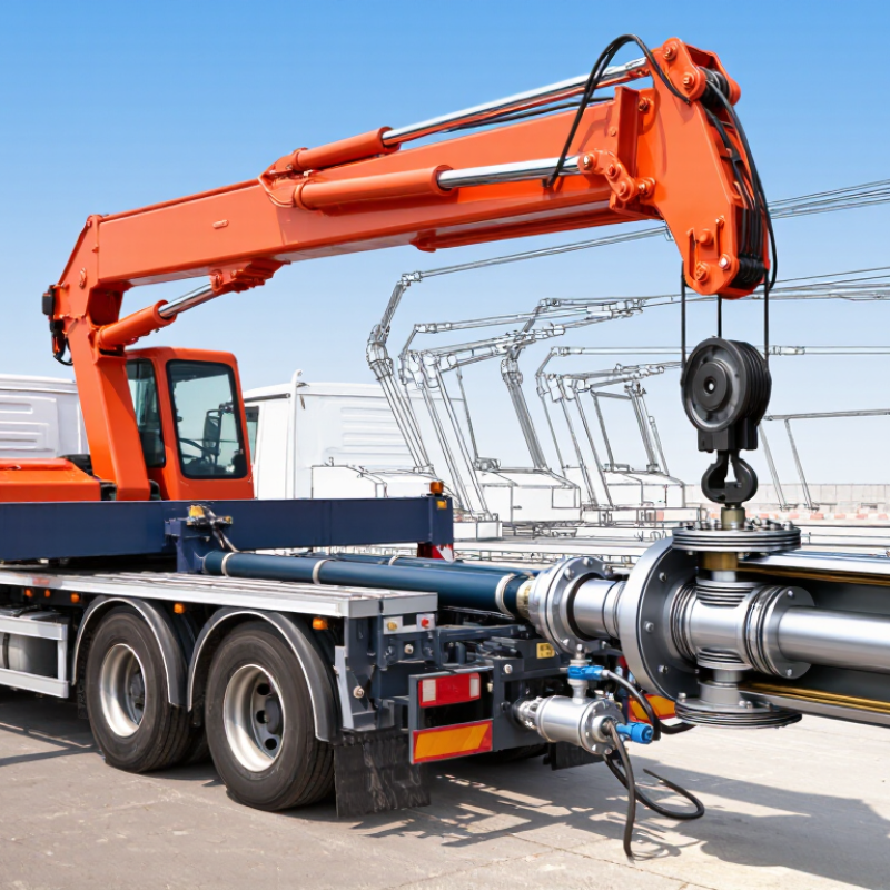
A Truck Crane Cylinder is a hydraulic actuator that creates controlled linear movement on a truck-mounted crane. It commonly raises the boom, extends telescopic sections, or positions stabilizing equipment. Inside its steel barrel, pressurized hydraulic oil pushes against a piston. The piston moves a chrome-plated rod. That rod transfers force to the crane structure.

The working process is direct, but not simple. A hydraulic pump sends oil through control valves and hoses. Oil entering one cylinder chamber moves the piston outward. Oil leaving the opposite chamber returns to the tank. Reversing the oil flow retracts the rod. Seals help maintain pressure, while the barrel and rod carry heavy mechanical loads. Performance depends on oil cleanliness, correct pressure, proper alignment, and the cylinder’s rated capacity.

Small details matter. A damp seal may leave a thin oil ring on the rod. A bent rod can cause uneven movement or rapid seal wear. Unusual noise may suggest trapped air, restricted flow, or a failing pump. These signs require careful inspection, not guesswork. Always compare testing procedures with the crane manufacturer’s service manual. Never rely only on appearance.

The term “truck crane cylinder” is not perfectly standardized. Different suppliers may describe lifting, telescopic, or outrigger cylinders differently. That can create confusion during replacement. Even experienced technicians can overlook mounting angles or hydraulic port specifications. A correct explanation must connect design, pressure, load, and maintenance. This guide examines how these cylinders work and why reliable inspection protects both equipment performance and job-site safety.
What Is a Truck Crane Cylinder and How Does It Work?

Truck Crane Cylinder: Definition and Role in Lifting Systems

A truck crane cylinder is a hydraulic actuator that converts pressurized oil into controlled movement. It usually contains a steel barrel, piston, rod, seals, and mounting joints. When hydraulic fluid enters one side, pressure pushes the piston. The rod then extends or retracts, moving the boom, stabilizer, or lifting arm.

Its role in the lifting system is precise and demanding. The cylinder supports boom elevation, load positioning, and sometimes crane stabilization. Unlike a simple mechanical strut, it allows gradual movement and adjustable force. A properly sized cylinder must match the crane’s load capacity, working angle, stroke length, and hydraulic pressure. In field inspections, uneven extension often points to trapped air, worn seals, contamination, or alignment stress. Small leaks matter. They can reduce lifting accuracy and create unsafe pressure loss. However, not every slow movement comes from the cylinder; the control valve and pump also deserve attention.

Tips: Keep the rod clean and lightly protected from moisture. Inspect seals, hoses, pins, and mounting points before operation. Never touch a suspected leak with bare hands, because hydraulic fluid can penetrate skin. Use the manufacturer’s service data for pressure checks. A visual inspection is useful, but it is not enough. Many failures begin inside the cylinder, where damage remains hidden until performance changes. Personally, I would not ignore a slight knocking sound; it may seem minor, yet it often deserves a closer inspection.

Main Components and Structural Design of a Crane Cylinder

What Is a Truck Crane Cylinder and How Does It Work?

Main Components and Structural Design of a Crane Cylinder

A truck crane cylinder is a hydraulic actuator that converts fluid pressure into controlled movement. Its main parts include the cylinder barrel, piston, piston rod, seals, gland, ports, and mounting clevises. The barrel contains pressurized oil, while the piston divides its internal chambers. Oil entering one chamber pushes the piston and extends the rod. Flow to the opposite chamber retracts it. Simple in principle.

Structural design determines how safely the cylinder handles lifting forces. A thick barrel resists internal pressure, while the rod must withstand compression, bending, and possible buckling. The piston and gland guide movement and reduce side loading. High-quality seals limit leakage, but they cannot correct poor alignment. In field inspections, uneven rod wear often reveals mounting stress before serious damage appears. Design calculations are essential, yet real working conditions can be less predictable than drawings suggest.

Tips: Check the rod for scratches, rust, and oil traces before operation. Inspect mounting pins and bushings for looseness. Keep hydraulic oil clean and use the specified pressure range. Never treat a leaking seal as a minor issue. A cylinder may still move, but its reliability is already changing. Consider temperature, dust, and repeated shock loads during maintenance reviews.

How Hydraulic Pressure Produces Cylinder Movement

What Is a Truck Crane Cylinder and How Does It Work?

A truck crane cylinder is a hydraulic actuator that converts fluid pressure into controlled movement. Inside its steel barrel, a piston separates two oil chambers. A polished rod connects the piston to the boom, jib, or support equipment. When a hydraulic pump sends pressurized oil into one chamber, the piston moves. The rod then extends or retracts, depending on the oil flow direction.

The process follows Pascal’s principle. Pressure applied to hydraulic oil travels through the sealed system with little loss. The cylinder’s force depends on pressure and piston area. A larger piston can produce greater lifting force, but it usually moves more slowly. Control valves direct oil through hoses and ports. Metering the flow helps the operator raise the boom smoothly instead of causing sudden movement. Relief valves also limit excessive pressure during heavy work.

In field inspections, I look for oil film, damaged rod surfaces, loose fittings, and uneven motion. These details often reveal seal wear or trapped air. Air makes the cylinder feel springy. That can reduce positioning accuracy. Temperature also matters because cold oil flows slowly, while overheated oil may damage seals. Not every slow cylinder needs a new pump. The valve, hose, filter, or load condition may be responsible. This is where diagnosis can become imperfect, especially when several faults appear together. Calibration and pressure testing should follow the equipment’s service specifications.

What Is a Truck Crane Cylinder and How Does It Work? - How Hydraulic Pressure Produces Cylinder Movement

System Element Primary Function How Hydraulic Pressure Produces Movement Key Dimensions or Data Typical Engineering Considerations
Hydraulic Cylinder Converts pressurized hydraulic-fluid energy into linear pushing or pulling force. Pressure acts on the piston area inside the cylinder. The resulting force moves the piston rod in or out. Force = Pressure × Effective Area The actual usable force is reduced by friction, seal resistance, and pressure losses in the circuit.
Cylinder Barrel Provides the sealed chamber in which the piston travels. Hydraulic fluid enters one side of the piston while fluid from the opposite side returns to the reservoir or control valve. Common materials include honed steel tubing; internal surface finish is critical for seal life. The barrel must withstand the system’s maximum working pressure and external bending loads.
Piston Separates the two fluid chambers and transfers hydraulic force to the rod. Pressure applied to the piston face creates a load that drives the piston along the barrel. Piston Area = π × Bore Diameter² ÷ 4 A larger bore produces greater force at the same pressure but generally requires more fluid for a given stroke.
Piston Rod Transmits cylinder force to the crane boom, jib, stabilizer, or another mechanical linkage. Rod extension produces one direction of movement; rod retraction produces the opposite direction. Usually chrome-plated or otherwise corrosion-resistant; diameter must resist buckling and side loading. The rod should primarily carry axial loads. Misalignment and side loads can damage the rod, guides, and seals.
Rod-End and Base-End Mounts Connect the cylinder to the crane structure and allow the cylinder to apply force through its intended line of action. As the rod moves, the mounting points transfer the linear force into angular boom or stabilizer movement. Mounting designs may use pins, spherical bearings, trunnions, or clevis connections. Pin alignment, bearing clearance, and structural strength affect stability, wear, and cylinder service life.
Hydraulic Pump Moves hydraulic fluid from the reservoir into the circuit and provides flow for cylinder movement. The pump creates flow. Resistance to that flow generates pressure when the cylinder is loaded. Cylinder Speed ≈ Flow Rate ÷ Effective Area Pump displacement and engine speed influence available flow and therefore cylinder operating speed.
Directional Control Valve Routes pressurized fluid to either the rod side or piston side of the cylinder. Moving the valve spool changes the flow path, determining whether the cylinder extends, retracts, or stops. Valve capacity is specified by allowable flow, pressure rating, and control characteristics. Metering the flow allows smoother starts, stops, and crane positioning.
Relief Valve Limits maximum hydraulic pressure and protects the pump, cylinder, hoses, and structural components. When pressure reaches the relief setting, excess flow is diverted back to the reservoir or another safe circuit path. Setting must remain below the rated pressure of the lowest-rated component in the protected circuit. A relief valve protects against overload pressure but does not replace correct load-chart and stability procedures.
Hydraulic Fluid Transfers energy, lubricates moving parts, removes heat, and helps protect internal surfaces from corrosion. Nearly incompressible fluid transmits pressure throughout the connected chambers and lines. Viscosity changes with temperature; contamination control is essential for reliable valve and seal operation. Use fluid that meets the equipment manufacturer’s viscosity, additive, and cleanliness requirements.
Cylinder Extension Force Determines the maximum theoretical push force available during extension. Pressure acts over the full piston area because the piston side is not reduced by the rod cross-section. Fextension = P × πD² ÷ 4 The force available at the crane mechanism also depends on lever geometry and mechanical advantage.
Cylinder Retraction Force Determines the theoretical pulling force available during rod retraction. Pressure acts on the annular area, which is the piston area minus the rod area. Fretraction = P × π(D² − d²) ÷ 4 Retraction force is lower than extension force for the same pressure and bore because the rod occupies part of the piston area.
Stroke Length Defines the maximum linear distance the piston rod can travel. Longer stroke allows greater boom or stabilizer movement, provided the surrounding structure permits it. Stroke is specified as the distance between fully retracted and fully extended rod positions. The cylinder must not be used as a mechanical stop unless it is specifically designed for that purpose.
Flow-Control Components Regulate fluid flow to control cylinder speed and movement smoothness. Restricting or metering flow changes the volume of fluid entering or leaving the cylinder per unit of time. Speed ≈ Flow Rate ÷ Area Excessive restriction can create heat and pressure loss, while uncontrolled flow can cause abrupt movement.
Counterbalance or Load-Holding Valve Helps prevent unintended movement when a suspended or raised load tends to drive the cylinder. The valve restricts return flow and opens in a controlled manner when pilot pressure and operating conditions are suitable. Valve setting depends on load, circuit pressure, cylinder area ratio, and application requirements. It supports load control but does not eliminate the need for mechanical stability, correct setup, and safe operating practices.
Seals and Wiper Prevent internal and external leakage while keeping dirt and moisture away from the cylinder interior. Seals maintain separation between pressure chambers; the wiper removes contaminants from the retracting rod. Seal materials must be compatible with fluid type, pressure, temperature, and rod speed. External leakage, damaged chrome, scoring, or rapid fluid loss indicates that inspection and repair may be required.
Movement Sequence Describes how operator input becomes controlled crane movement. Operator command → control valve shifts → pump flow is directed → pressure develops against the load → piston and rod move. Movement depends on flow rate, load resistance, cylinder geometry, and valve response. Smooth movement requires coordinated control of pressure, flow, load moment, and crane stability.

The Cylinder’s Role in Truck Crane Lifting Operations

A truck crane cylinder is a hydraulic actuator that creates controlled linear movement. In lifting operations, it commonly raises the boom, extends sections, or positions stabilizers. Hydraulic oil enters one side of the cylinder and pushes the piston. The attached rod then moves with considerable force. Force depends on oil pressure and piston area, while movement speed depends on oil flow.

The boom cylinder directly affects lifting geometry. A small change in boom angle can alter the working radius and reduce the permitted load. Operators must compare the actual radius, boom length, and load weight with the crane’s load chart.

The control valve meters oil gradually, helping prevent sudden movement. Counterbalance valves can hold the boom if hydraulic flow is interrupted. This protection matters when a suspended load begins to swing.

During field inspections, the rod should look smooth and dry. Even a thin oil film may signal seal wear. Check for bent rods, damaged hoses, loose pins, and unusual sounds during operation. A clean cylinder is not automatically a healthy cylinder.

I have seen operators blame the pump when the real issue was a leaking piston seal. That mistake wastes time and may increase risk. Pressure testing and maintenance records provide stronger evidence than visual judgment alone. The cylinder should never be treated as an isolated part; its condition affects stability, load control, and the operator’s response time.

Maintenance, Safety, and Common Cylinder Problems

A truck crane cylinder converts hydraulic pressure into controlled movement. It raises a boom, extends a section, or positions an outrigger. Inside, pressurized fluid pushes a piston through a sealed barrel. The rod then transfers force to the crane structure. Small seal damage can become a serious stability issue. A clean-looking cylinder is not necessarily healthy.

Maintenance should begin with the crane parked on firm, level ground. Lower the boom when possible, engage the required support procedure, and release hydraulic pressure. Never place hands near a suspected leak. Escaping fluid can penetrate skin, even through a tiny pinhole. Inspect the polished rod for rust, dents, and uneven wear. Check hose fittings, mounting pins, weld areas, and the barrel for cracks. Wipe away dirt before inspection; grime can hide fresh oil. Record leaks and unusual movement. Do not rely on memory. Pressure can be deceptive.

Common problems include seal leakage, cylinder drift, slow movement, and jerky extension. Drift may indicate worn seals, a faulty control valve, or internal bypassing. Slow operation can result from contaminated fluid, restricted hoses, or low system pressure. A bent rod may point to overload, poor alignment, or side loading. Do not keep operating to see if it improves. Stop, isolate the equipment, and use qualified service personnel for pressure testing. Replacing seals alone may fail if the rod or bore is scored. Maintenance schedules help, but working conditions matter more. Dust, salt, and shock loads demand closer inspections.